Principles of assembly drawings
Introduction
An assembly drawing shows how each of the different parts of a finished product fit together. Sectional views may be drawn for the purpose of making each part on the drawing as clearly identifiable as possible.
In most cases dimensions are entirely omitted on assembly drawings. Some machines or structures, however, require a few assembly dimensions for important center distances, or for location of valves, switches, and other features.
Assembly dimensions are occasionally needed to guide the shopman in properly installing the various parts in their correct locations.
Assembly drawings are drawn full size whenever practical. For this reason, large sheet sizes are often used for assembly drawings. Sheet sizes as large as 34 inches by 5 feet, and larger, are frequently used for assembly drawings.
(See Table 7, "Standard Sizes of Drawing Sheets.")
Kinds of assembly drawings
Layout or design assembly drawings
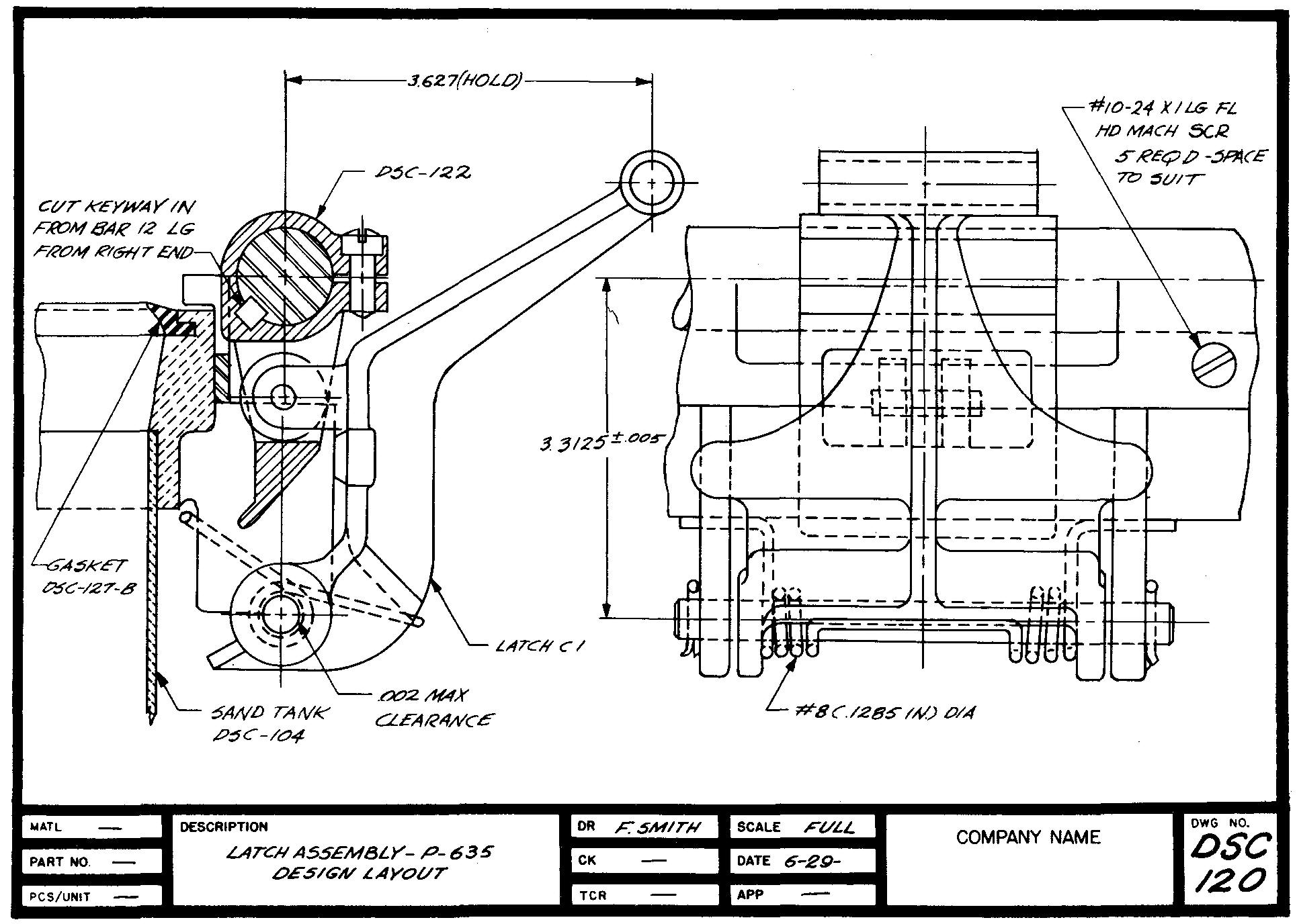
One of the first drawings to be made to describe an idea, a layout or design assembly drawing, is shown in Fig. 17-1.
Fig. 17-1. A layout or design assembly drawing
This drawing is usually prepared by the design engineer, together with any necessary calculations and freehand sketches. It is drawn to scale, usually full size, depending upon the size of the structure.
A layout assembly drawing generally shows only the important features of the product. Most of the minor details such as nuts, bolts, screws, and cotter pins are omitted.
Essentially, the layout is a graphic model of the assembled parts. We might think of this drawing as a kind of a test. By drawing the views of the various parts, each fitting with one another, the engineer can test the appropriateness or function of each individual part.
Also, he can determine the general appearance and size of each part as he draws it in its proper location.
The engineer may also indicate other important information, either on the drawing or on a separate sheet. Such information may include a listing of the required materials; notations for clearances and interferences; and additional descriptions of specific parts which may be required, such as keys, bushings, and fasteners.
Data of this nature are very necessary to the machine draftsman who works from the layout or design assembly as he prepares the detail drawings. The shopman manufactures the parts by using the detail drawings. The assembly drawings are used as a guide in assembling the various parts in their proper positions.
Working assembly drawings
These assembly drawings, illustrated in Fig. 17-2, can be used to a good advantage when the product contains a limited number of parts.
Fig. 17-2. A working assembly drawing
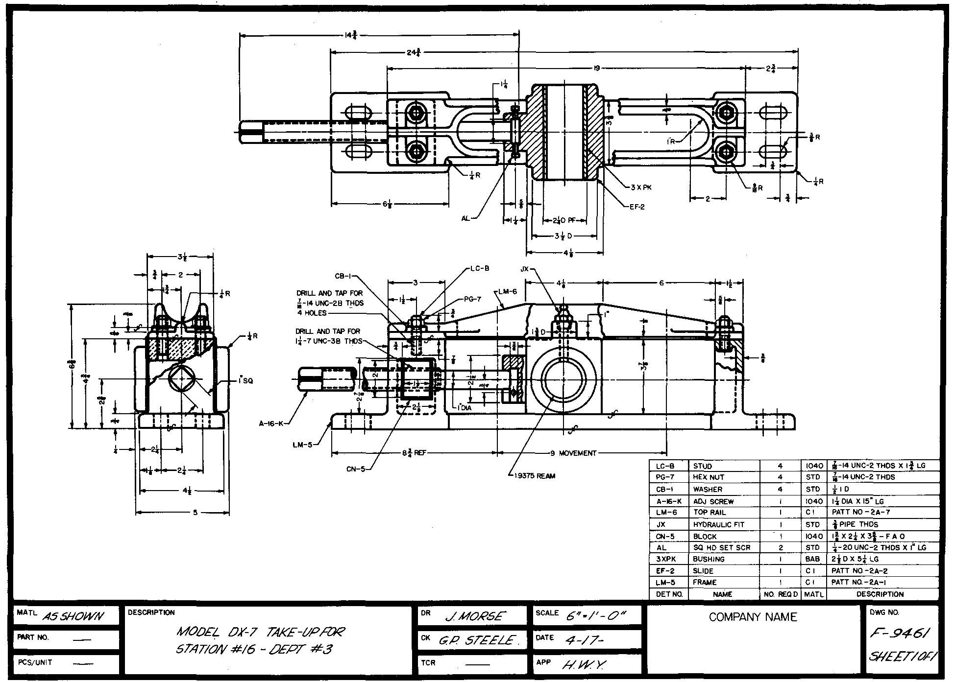
In this case, all of the detail description applying to the parts, such as dimensions, notes, and symbols, may be placed directly on the assembly views.
Thus, the need for making a separate set of detail drawings is usually eliminated. The single drawing is in itself complete and usually requires no additional drawings to describe the product.
Industries are using this kind of assembly drawing more and more today. There is a saving of time in placing the specifications for all the parts directly on the views of the assembly drawing.
Also, it is considered an advantage to group all information on one sheet rather than to use two or more sheets for the same purpose.
It must be understood, however, that only products which consist of reasonably few and simple parts are prepared in this manner. Because of possible confusion and misunderstanding, a working assembly drawing would not be prepared for products consisting of many and complex parts.
Diagram assembly drawings
An assembly drawing such as the one shown in Fig. 17-3 is prepared for piping layouts, structural work, electrical diagrams, and industrial floor plan layouts.
Fig. 17-3. A diagram assembly drawing
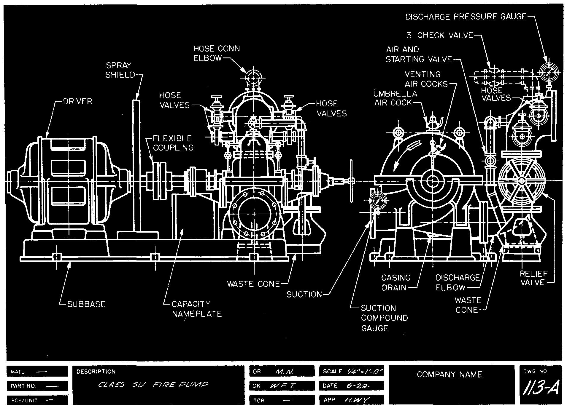
Most features are shown symbolically or are represented by as few lines as possible. The chief requirement of such a drawing is to show the general shape and location of the various parts.
Due to the large sizes frequently involved (on a floor plan, for example), diagram assembly drawings are usually made to a reduced scale.
Diagram assembly drawings may also be prepared pictorially. Since these drawings are general in nature, only the key parts of features are usually labeled.
Final or erection assembly drawings
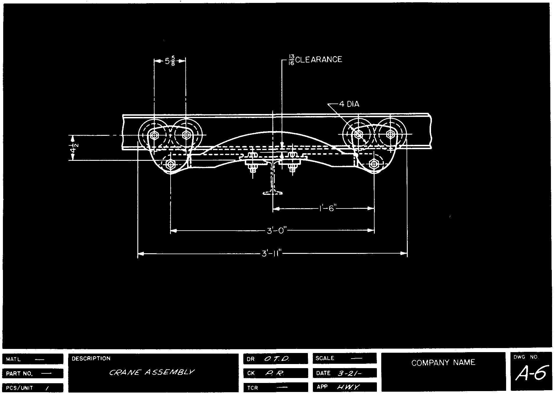
The assembly drawing shown in Fig. 17-4 is drawn to an accurate scale. Such a drawing is usually made by tracing a previously prepared layout or design assembly drawing; if this is done, previously omitted parts are drawn in their proper positions.
Fig. 17-4. A final or erection assembly drawing
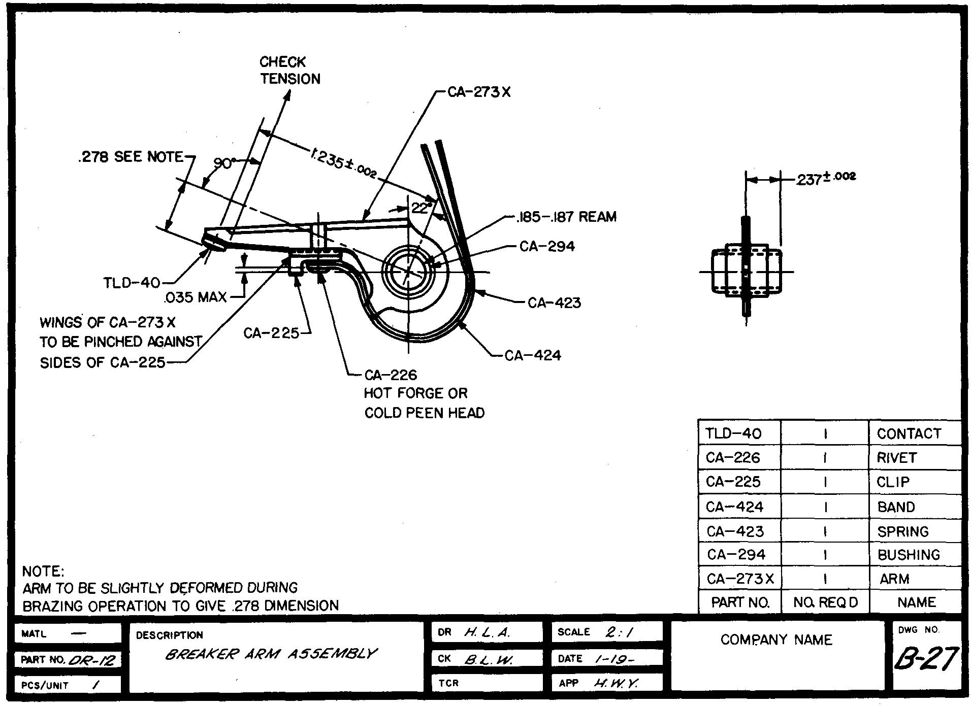
The erection assembly drawing may also be prepared by tracing the views of the parts from the detail drawings. The draftsman begins by examining each part to observe its function when assembled with the other parts.
The parts are next carefully drawn or traced on the assembly drawing; this step serves as a check of one part to another. Necessary clearances and interferences of the mating parts may be conveniently examined.
The final assembly drawing is
also used for planning methods of assembling and dismantling the various parts.
Hidden lines are kept to an absolute minimum. Only those hidden lines which are
absolutely necessary for a complete understanding are drawn. Sectional views are
frequently used to show interior construction.
Unlike the design assembly drawing, this type of drawing is made as complete as possible. The final or erection assembly drawing is used as a reference throughout the manufacture, assembly, and inspection of the product.
Outline assembly drawings
Figure 17-5 shows an assembly drawing in which only the exterior features and the general appearance and arrangement of certain parts of the product are shown. Certain dimensions may be given, such as center distances, overall sizes, and mounting hole spacings.
Fig. 17-5. An outline assembly drawing
This kind of assembly drawing is commonly used for sales and catalog material, where only the general size and appearance of a product are required.
Dimensions are often listed in columns or tables on the drawing, especially when one illustration is used to describe several available sizes, as in Fig. 17-6. In general, each part of the product is drawn proportionately in size to each of the other parts, but the drawing is usually not made to an accurate scale.
Fig. 17-6. An outline assembly drawing

Parts are generally represented by as few lines as possible. Complicated detail of each part is omitted for clarity.
Subassembly or unit assembly drawings
Figure 17-7 is a drawing of a product which shows only a limited group of parts belonging to an entire assembly of parts.
Fig. 17-7. A subassembly or unit assembly drawing

It is used for complicated products when it would be confusing to show all of the parts assembled on one drawing. Subassembly drawings represent a breakdown of the assembled product into small groups of parts.
For example, a set of drawings for a machine lathe might consist of separate subassembly drawings of four groups of parts: gear box, headstock, tailstock, and carriage.
Pictorial assembly drawings
The assembly drawing shown in Fig. 17-8, usually referred to as an exploded drawing, is used principally for catalog or display purposes.
Fig. 17-8. A pictorial assembly drawing
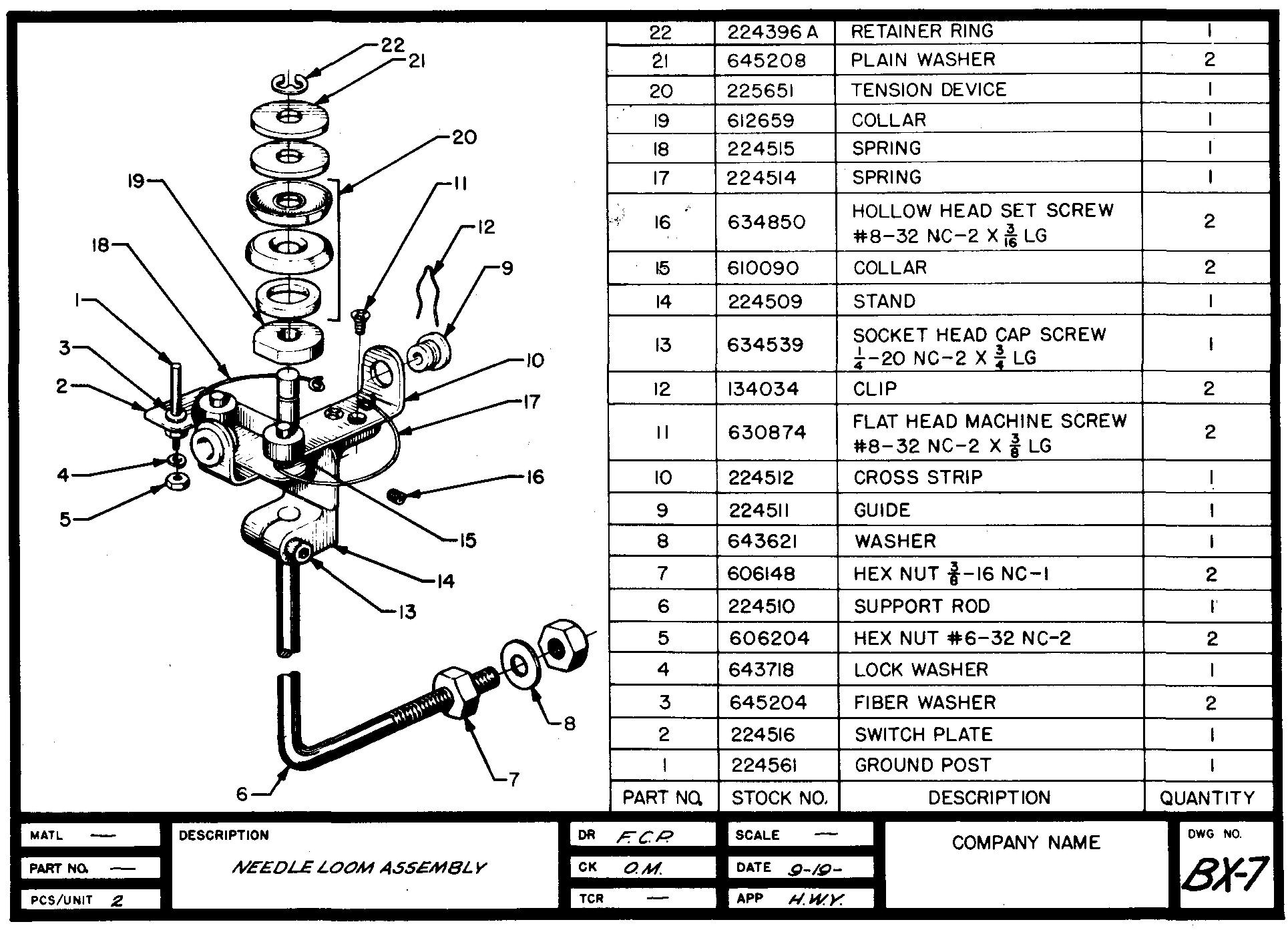
Some companies also use such drawings to instruct trainees in assembly line techniques in their training programs. Parts lists and other descriptive material may be placed on the drawing or may accompany it on other sheets. Companies have found pictorial assembly drawings to be more easily understood than any other type of drawing, especially for personnel with limited technical training.
Part numbers
As an aid in identifying each of the separate parts or items on an assembly drawing, each part is designated by a number. A leader is drawn connecting the number to the part shown in the view. Part numbers are frequently enclosed in a 3/8-inch or 1/2-inch diameter circle, sometimes called a balloon.
On the detail sheet, the corresponding part number is placed directly below the views of each part.
The bill of material, or parts list
Figure 17-9 illustrates a final assembly drawing of a jack plane, which is a tool used in woodworking. Also on the sheet is a list of all the parts required to assemble one complete plane.
Fig. 17-9. A final assembly drawing
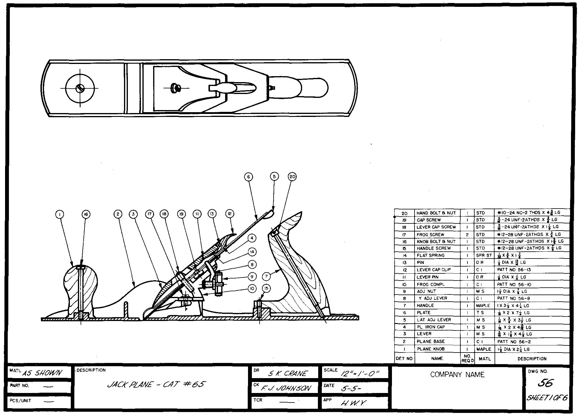
The list, called a bill of material (or parts list), may be placed directly on the assembly sheet (which is the usual case) or on a separate sheet. The parts list is usually placed in the region above the sheet title block.
The lowest part number should be placed at the bottom with successive numbers reading up the list. Should additional parts be later required, numbers may be assigned and added to the top of the list.
The draftsman may rule off conveniently spaced lines on a drawing sheet, or he may use a sheet which has been especially printed for this purpose.
Some companies use commercially prepared decalcomanias (gummed transparent sheets), which may be applied to the backs of the drawings. Items can be lettered in the spaces between the ruled lines which appear visible from the front of the drawing.
Most companies have established a standard size for bills of material. In the absence of any standard, it is suggested that the total width be approximately 6 inches with the columns spaced according to the required data to be included. Line spacings should be at a minimum of 1/4 inch apart. Lettering of 1/8 inch high is standard.
Drawing sheets with a pre-printed parts list have been found to save considerable drafting time. More and more companies are using this method.
The parts list usually contains a listing of items similar to that shown in Fig. 17-9. The following paragraphs explain the titles which describe the contents of each column.
Detail, part, or item numbers
A number is assigned to each different part. Usually, parts made by similar processes are grouped within a consecutive series of numbers: all castings, all forgings, all purchased parts, and so on.
Castings and forgings are generally assigned the lowest numbers, items to be manufactured next, and finally, the purchased parts are placed at the top of the list.
Part names
A title is usually given to each part as an aid in identifying the different parts of the product.
Number required
This part of the bill of material lists the total of the identical parts required for one complete product.
Materials column
This column contains the specification of the required material for each part. In many companies, selection of the material for some of the purchased parts may be left to the discretion of the manufacturer. In this case the notation STD (Standard), PUR (Purchased), or COMM (Commercial) is used.
Stock sizes or descriptions
One column of the bill of material is devoted to a size description for each part. The column usually includes the stock or rough size of the parts before machining. An additional number may be assigned to castings and forgings so that different parts may be readily identified at the foundry or forge shop. Thread data are often included in this column for certain parts.
Remarks
Some companies prefer to include a column labeled Remarks. Here, such data as the weight of each part, the surface treatment, the drawing numbers, and other special information not suited to any other column may be listed.
Review questions
1. What is the purpose of an assembly drawing?
2. Describe a layout or design assembly drawing.
3. Describe a working assembly drawing.
4. Would a working assembly drawing be suitable for showing products containing a great number of parts? Explain.
5. What is the advantage of grouping all of the information on one sheet (as on a working assembly drawing) rather than using two or more sheets for the same purpose?
6. What are the uses for a diagram assembly drawing!
7. How are most of the features shown on this kind of drawing?
8. How is a final or erection assembly drawing prepared?
9. What type of lines are kept to an absolute minimum on final or erection assembly drawings?
10. How are assembly drawings of this kind used?
11. What is the purpose of an outline assembly drawing!
12. Why are complicated features and details usually omitted on outline assembly drawings?
13. What is meant by a subassembly drawing!
14. Why are part numbers applied to assembly drawings?
15. Where on the assembly sheet is the parts list or bill of material usually placed?
16. Why should the numbering of parts in the bill of material begin with the lowest number?
17. What is included in a parts list?
18. Tell in what column the following information would be found:
a. Quantity of similar parts.
b. Part number for a cast part.
c. Hardness number for heat treatment.
d. Standard purchases.

![]()